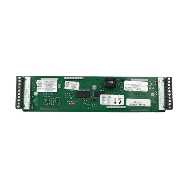
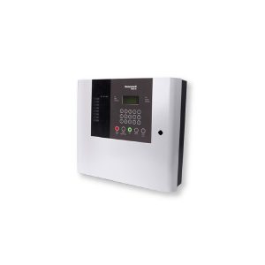
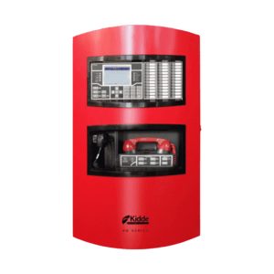
Kidde VM-SLCXB Single Loop Driver Controller
Key Features:
- One Class A or Class B intelligent device loop standard, optional loops brings control panel capacity to 1000 devices
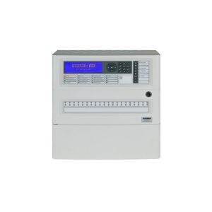
- 24-line by 40-character backlit LCD capable of displaying eight simultaneous events
- Optional voice evacuation and firefighter’s telephone
- Suitable for low frequency signaling in sleeping areas
- Optional network interface slots on the back of a swingable mounting chassis
- Electronic addressing with automatic device mapping
- Optional Ethernet port for diagnostics, programming
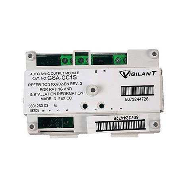
- Supports strobe synchronization
- Supports up to 30 R-Series remote annunciators with either Class A or Class B wiring
- Networkable up to 24 VM control panels
- Patented Voltage Boost™ technology delivers constant voltage even at low battery power
- 10 Amp UL listed power supply
- Integrated Carbon Monoxide gas sensing
- 4 On-board Notification Appliance Circuits
- Room for 3 optional front panel LED/Switch modules
- Optional: Ethernet interface, earthquake hardening
Description
Overview
Kidde’s VM-SLCXB Single Loop Driver Controller was designed with leading edge computing power, yet it is still highly flexible. It can be used in a simple, single building as a standalone system and can also be part of a network with thousands of points across multiple buildings. Unlike other mid-range systems, it has an optional voice evacuation function making it a cost-effective solution for multiple applications.
Efficient, cost-effective networking
The VM-SLCXB Single Loop Driver Controller network can comprise up to 8 control panels – enough to serve the needs of most campuses and larger buildings. Highly efficient RS485 connectivity, plus fiber-optic communications deliver faster response times and more sophisticated diagnostic capabilities, while remote annunciation solutions keep basic monitoring and control always within reach.
Audio that speaks for itself
Kidde VM-SLCXB features 3 channels of integrated digital audio with up to 2 minutes of programmable message storage. An optional paging control center includes a paging microphone which can be added as a firefighters’ telephone. Auxiliary inputs are available for mass notification operations and connection to external systems.
Versatility built right in
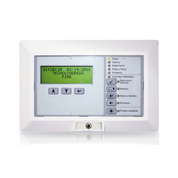
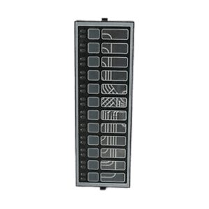
The control panel has room for 3 fully programmable front panel switch/LED strips. Each strip includes 12 switches with 2 associated LEDs (one quad-color, and one yellow), and a custom label area. LED color designations can be assigned by the installer.
Perfect for retrofits
This unit is particularly well-suited to retrofit applications. All connections are made over standard wiring – no shielded cable required. This means that existing wiring can be used to upgrade a legacy control panel to VM-SLCXB technology without the expense or disruption of rewiring the entire building.
Clear-cut remote annunciation
Up to 30 R-Series LCD, LED annunciators and driver interface cards may be configured for each control panel on the VM-SLCXB network. Compatible annunciators include a range of LED and LCD models that provide zone or point annunciation, as well as common control capabilities. Kidde VM-SLCXB also supports graphic annunciation with optional graphic annunciator interface modules. Each interface provides common control, indicators, and 32 LEDS. Expansion units provide 48 led outputs.
Power that goes the distance
Edward’s patented Voltage Boost™ technology delivers constant 22.5 Vdc on NAC and AUX circuits – even at low battery power. This means lighter gauge cable can be used for equivalent distances compared with conventional power supplies, or longer wire runs on the same gauge cable. Either way, this breakthrough technology saves time and equipment costs, making VM-SLCXB not only a high-performance solution — but a cost-effective one as well.
Scalable IP and Cellular Communications
Several popular third-party IP/Cellular communicators have been tested with the VM-SLCXB control panel and are compatibility listed to UL864. The IP/Cellular communicators meet NFPA72 2013 edition requirements for sole or secondary transmission paths. Using IP/ Cellular communicators can reduce the cost of ownership by eliminating POTS lines.
Technical Specifications
| Voltage | 19.0 VDC nom., 24 VDC max. | |
| Standby Current (one circuit) | 144 mA at 24 VDC | |
| Alarm Current (one circuit) | 204 mA at 24 VDC | |
| Standby Current (two circuits) | 264 mA at 24 VDC | |
| Alarm Current (two circuits) | 336 mA at 24 VDC | |
| Smoke power Voltage | 24 VDC max. | |
| Smoke power Current | 19.95 mA | |
| Designation | Class B or Class A | |
| Capacity | 125 detector and 125 module addresses per circuit | |
| Resistance | 100 Ω max. | |
| Capacitance | 0.5 μF max. | |
| Wire size | 12 to 18 AWG (1.0 to 4.0 mm²) max | |
| Temperature | 32 to 120°F (0 to 49°C) | |
| Relative humidity | 0 to 93% noncondensing |


